MIL-DTL-16036M(SH)
a.
Nut and jam nut
b.
Belleville washers (plain)
c.
Clip-on types of nuts formed by stamping a thread-engaging impression in a flat piece of metal
d.
Single-thread engaging nuts formed by stamping a thread-engaging impression in a flat piece of metal
e.
Setscrews
f.
Liquid threadlocking adhesive
3.5.13 Welding. Requirements for welding and allied processes shall be in accordance with
S9074-AR-GIB-010/278 with the following exception. Welding practices in accordance with applicable American
Welding Society (AWS) specifications may be used for welding applications not referenced in
3.5.14 Mechanical shock. Sections of all switchgear groups shall meet the Grade A shock requirements of
MIL-S-901 when tested as specified in 4.4.3.3.
3.6 Insulation.
3.6.1 Insulating material. In order to restrict the use of material which might catch fire or emit fumes when
exposed to flame, the quantity of insulating material shall be kept to a minimum and used only where necessary to
provide electrical insulation between live parts and to ground. Insulating material for bus supports and spacers, fuse
bases, and other similar parts shall be in accordance with MIL-E-917, a minimum of a Class B insulation system.
3.6.2 Insulation distances. Insulation distances in air and surface creepage distances on insulating materials for
equipments shall conform to the applicable specifications. For all other live parts, such as bus work, and bus to
component line-side and load-side stud connections on circuit breaker bases which have a frame size greater than
100 amperes, values shall meet the applicable creepage and clearance distances in table I. See 3.10.18 for
100 ampere circuit breaker connection requirements.
3.6.2.1 Insulating material. Insulating material used to obtain electrical clearance shall be a minimum of 1/8
inch thick when there is a possibility of impact or abrasion to the insulating material resulting from high-impact
shock or vibration. Otherwise, it may be 1/16 inch thick. Insulating material shall be secured by through-bolting.
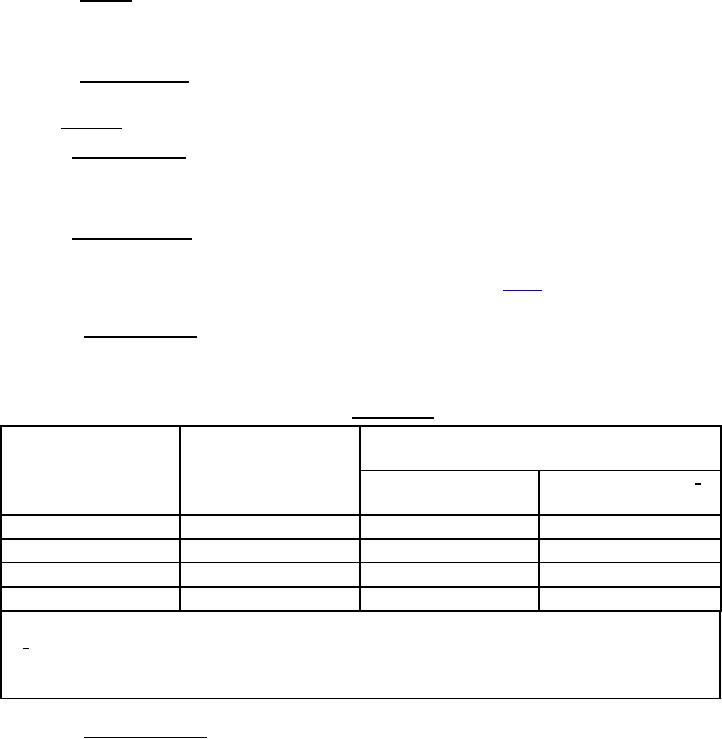
TABLE I. Switchboards.
Insulation distances to ground or to opposite polarity
surface creepage
In air
Voltage
(inches)
Top and flat surfaces 1/
Bottom and side surfaces
(inches)
(inches)
125 AC or DC
0.50
0.94
1.13
230 AC
0.63
1.20
1.50
500 AC or DC
0.78
1.56
2.00
1000 AC
1.31
2.50
3.340
NOTE:
1/
Values for top creepage apply to flat surfaces or to curved surfaces presenting sufficient irregularities to
permit accumulation of dust and moisture. Values are not intended to apply to simply cylindrical surfaces
having a radius of 3 inches or less where side creepage values will apply.
3.6.2.2 Insulation resistance. Insulation resistance from phase to phase and from any phase to the frame/chassis
of the switchgear shall not be less than 10 megohms at 77 °F (25 °C).
27
For Parts Inquires submit RFQ to Parts Hangar, Inc.
© Copyright 2015 Integrated Publishing, Inc.
A Service Disabled Veteran Owned Small Business