MIL-DTL-16036M(SH)
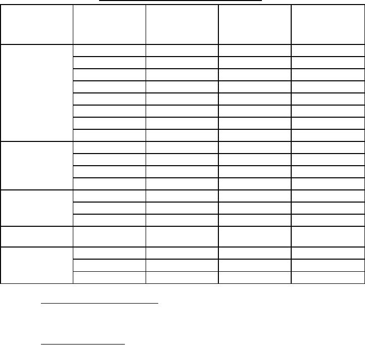
TABLE II. Ampere rating of rectangular bus bars placed on edge Continued.
Copper bus, silver
Cross-sectional
Copper bus, silver
Number of bars
Size of bars
surface, AC
area (square
surface, DC ampere
parallel
(inches)
ampere rating, 60
inches)
rating
Hz
2 (1/4 inch apart)
1 x 1/4
0.500
650
650
1-1/2 x 1/4
0.750
950
950
2 x 1/4
1.000
1,350
1,370
2-1/2 x 1/4
1.250
1610
1610
3 x 1/4
1.500
1,825
2,000
4 x 1/4
2.000
2,280
2,530
5 x 1/4
2.500
2,740
3,100
6 x 1/4
3.000
3,140
3,630
3 (1/4 inch apart)
3 x 1/4
2.250
2,200
2,620
4 x 1/4
3.000
2,660
3,110
5 x 1/4
3.750
3,200
3,830
6 x 1/4
4.500
3,600
4,560
4 (1/4 inch apart)
3 x 1/4
3.000
2,650
3,130
4 x 1/4
4.000
3,020
3,870
5 x 1/4
5.000
3,450
4,750
4 (2 pairs/phase, 3/4
6 x 1/4
6.000
4,000
----
inch between pairs)
4 (2 pairs/phase 2-
5 x 1/4
5.000
4,200
----
1/2 inches between
6 x 1/4
6.000
5,000
----
pairs
8 x 1/4
8.000
6,400
----
3.10.6 Grouping and arrangement of bus bars. Particular attention shall be given to the grouping and
arrangement of buses for AC (60 Hertz and above) currents near magnetic material, since proximity of such material
will create additional heating, thereby interfering with the dissipation of heat from conductors and reducing their
capacity.
3.10.7 Cabling for circuit breakers. Where single conductor cable is used for connection to circuit breaker,
cables shall be securely bound together with nonflammable cord and secured to the supports as necessary to prevent
distortion under short circuit conditions. Cable runs shall not come in contact with the bus bars except at the bus bar
terminating end of the cable. Binding shall be applied in such a manner that it will not cut into the cable insulation
due to the forces exerted under short circuit conditions. Binding shall be especially heavy where cables turn out of
the pack. Terminal lugs shall be used for terminating cable at the circuit breaker terminals and at the bus bar.
Through-bolts shall be used for securing the cable terminal to the bus bar. No more than two cable terminals shall
be clamped by one bolt and when two are used they shall be placed on the opposite sides of the bus. Cables shall be
neatly formed and, where their length exceeds approximately 12 inches, they shall be supported by the switchboard
structure and not by the bus bars.
31
For Parts Inquires submit RFQ to Parts Hangar, Inc.
© Copyright 2015 Integrated Publishing, Inc.
A Service Disabled Veteran Owned Small Business