MIL-DTL-2212K(SH)
3.16.6.2.1.8 Bulb size. The temperature switch bulb size shall be designated by the single letter symbol as
follows:
A - (3/8 inch by 3 inches)
B - (11/16 inch by 35/8 inches)
C - (11/16 inch by 8¼ inches)
D - (11/16 inch by 12 inches)
E - (11/8 inches by 6½ inches)
F - (11/8 inches by 14½ inches)
G - (11/8 inches by 30 inches)
H - (11/16 inch by 3 inches)
I - (11/16 inch by 43/8 inches)
N - Special (specified size other than a standard size)
3.16.6.2.1.9 Dimensions. The temperature switch dimensions shall be designated by a single letter symbol as
follows:
A - For temperature switch:
Mounting hole separation distance: 213/32 inches with the space between left-side mounting hole and the
housing edge as 13/16+1/8 inch and the space between the left-side mounting hole and the lower mounting hole
is 39/32 inches vertically and 21/32 inch horizontally, hole to hole tolerance is ±1/32 inch.
Switch box housing (maximum): 35/16 inches (height) by 5¼ inches (width) by 53/16 inches (depth).
Direct sensor housing (maximum): 2½ inches.
Remote sensor housing (maximum): 5 inches.
B - Special (other than the standard dimensions)
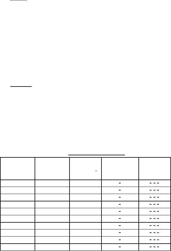
TABLE IV. Range for temperature switches.
Maximum
Maximum
Operating
allowable
proof
Optimum
temperature
Designator
temperature 1/
variation from
differential
range (°F)
(°F)
setting (°F)
4/
2/, 3/, 5/
1
-20 to 0
-
4/
2/, 3/, 5/
2
0 to 50
-
4/
2/, 3/, 5/
3
30 to 90
120
4/
2/, 3/, 5/
4
90 to 150
190
4/
2/, 3/, 5/
5
140 to 200
240
4/
2/, 3/, 5/
6
190 to 240
270
4/
2/, 3/, 5/
7
230 to 280
310
4/
2/, 3/, 5/
8
260 to 320
350
4/
2/, 3/, 5/
9
290 to 360
380
4/
2/, 3/, 5/
10
300 to 400
430
16
For Parts Inquires submit RFQ to Parts Hangar, Inc.
© Copyright 2015 Integrated Publishing, Inc.
A Service Disabled Veteran Owned Small Business