MIL-DTL-2212K(SH)
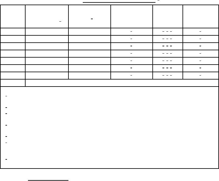
TABLE III. Range for differential pressure switches. 1/
Maximum
Adjustment
allowable variation
Maximum proof
Optimum
Connection for
operating/working
Designator
pressure 2/ (PSI)
from setting
differential
pressure supply
pressure range 1/
(plus or minus)
0.3 to 3 lb/in2
6/
4/, 5/, 7/
3/
1
5
5 to 30 lb/in2
6/
4/, 5/, 7/
3/
2
80
10 to 70 lb/in2
6/
4/, 5/, 7/
3/
3
125
20 to 150 lb/in2
6/
4/, 5/, 7/
3/
4
200
25 to 250 lb/in2
6/
4/, 5/, 7/
3/
5
400
100 to 800 lb/in2
6/
4/, 5/, 7/
3/
6
900
200 to 1300 lb/in2
6/
4/, 5/, 7/
3/
7
2000
8
Special (other than a standard range)
NOTES:
1/
Unless otherwise specified (see 6.2), for differential pressure switches, the ranges to be specified are the
operating pressure range and the resetting differential are relative to pressure difference.
2/
Unless otherwise specified (see 6.2), is in gauge pressure.
3/
Unless otherwise specified (see 6.2), type of connection shall be in accordance with 804-1385850 that is, a
mechanical threaded connection. Straight threads shall be standard for all new construction.
4/
Manufacturer's name and part number shall be given on the identification plate by which to obtain from
manufacturer all the information for which headings are given in this table.
5/
Shall be as specified (see 6.2).
6/
Repeatability of all switches shall be within 1 percent of the maximum proof pressure for all switches rated for
200 PSI and above and within 0.5 percent of the maximum proof pressure for all others. Repeatability, plus
operator error, plus gauge error equals maximum allowable variation from setting (tolerance).
7/
Differentials (make or break) will vary widely due to applications. Switch capabilities shall be as specified
(see 6.2).
3.16.6.2 Temperature switches. Temperature switches shall have the following features:
a.
Temperature switches shall meet the vibration requirements of 3.17.2.4.
b.
Temperature switches shall meet the shock requirements of 3.17.3.4.
c.
Temperature switches shall be electromechanical unless otherwise approved by the contracting activity.
d.
Electromechanical temperature sensing element to be diaphragm and bellows.
e.
Sensing bulb and capillary tube dimensions may differ as applicable.
f.
Temperature ranges and differentials specified by the manufacturer.
g.
Sensing bulbs of temperature control shall be mounted in the position specified by the manufacturer.
14
For Parts Inquires submit RFQ to Parts Hangar, Inc.
© Copyright 2015 Integrated Publishing, Inc.
A Service Disabled Veteran Owned Small Business