MIL-PRF-17773C(SH)
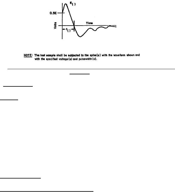
FIGURE 2. Acceptable wave shape for radiated susceptibility, magnetic and electric fields, spikes and power
frequencies.
4.6.12.2 Power frequency. The switch shall not exhibit any malfunction, degradation of performance or
deviation from specified indications when 20 amperes are applied to the test wire at 60 and 400 Hz.
4.6.13 Power test. Power tests shall be conducted in both steady-state and transient modes for the following in
accordance with MIL-STD-1399-300 during steady-state operation and during transfer at 180 degrees out of phase,
with line capacitance to ground of 100 µf per phase and a load with a power factor of 1 at 20 amps:
a.
Voltage and frequency tolerance
b.
Voltage and frequency transient tolerance
c.
Voltage spike
d.
Emergency condition
e.
Grounding
f.
User equipment power profile (at no load)
g.
Current waveform
h.
Equipment (insulation resistance)
i.
Voltage and frequency modulation
4.6.14 Chassis leakage current. The switch shall be tested for chassis leakage current in accordance with MIL-
E-917.
4.6.15 Compatibility with active ground fault detector circuit. When specified (see 3.4.37 and 6.2), the bus
transfer switch shall be tested with an active ground fault detector circuit utilizing a 500-VDC power supply and
shall:
a.
Have a source-to-source impedance as high as possible, but no less than 0.5 megohm at 122 °F (50 °C).
b.
Have a minimum source-to-ground impedance of at least 10 megohms.
c. Not cause a low-impedance to ground fault condition detected on one source to be imposed on, transferred
to, or reflected on the other source.
22
For Parts Inquires submit RFQ to Parts Hangar, Inc.
© Copyright 2015 Integrated Publishing, Inc.
A Service Disabled Veteran Owned Small Business