MIL-PRF-17773C(SH)
3.4.10 Auxiliary switches. Unless otherwise specified (see 6.2), ABTs over 100 amps shall be provided with
one double pole, double throw (DPDT) auxiliary switch, and ABTs 100 amps and under shall be provided with one
single pole, double throw (SPDT) auxiliary switch for remote indication of the supply line connected to the load
circuit or for a function limiting device, or both. The auxiliary switch contacts shall be wired to a terminal board in
the ABT for connection to the remote equipment. Auxiliary switches shall have a minimum rated continuous
current of 5 amps and a rated voltage of 500 VAC and 250 VDC and meet the endurance requirements as specified
in Method II, Table X.
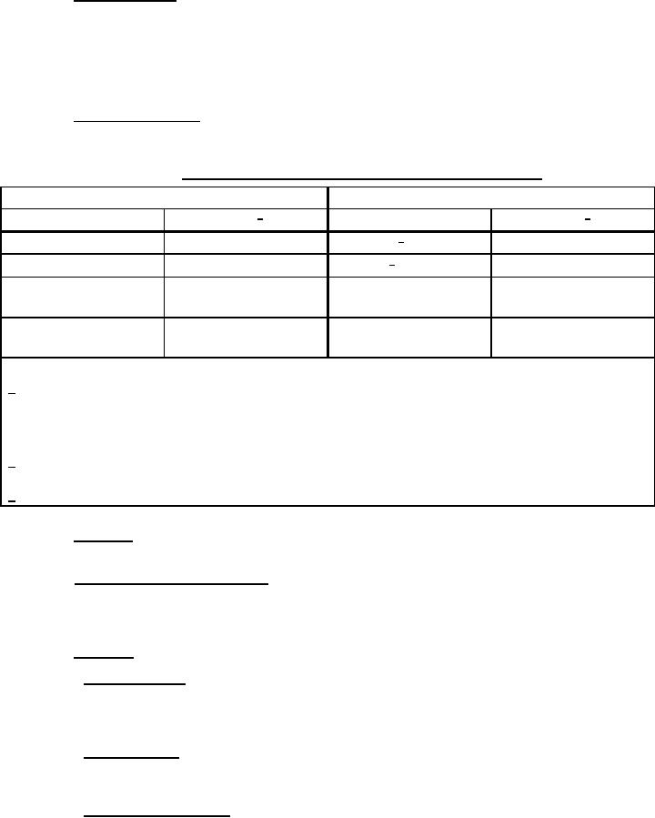
3.4.11 Switching mechanisms. Switching mechanisms of bus transfer switches shall use contactors, circuit
breakers, or rotary snap switches as specified in Table VI.
TABLE VI. Circuit breaker types and contactor sizes for bus transfer switches.
Manual
Automatic
Type 1/
Type 1/
Amperes (A)
Amperes (A)
Above 600 3/
Greater than 250
AQB
ACB
25 to 600 2/
250 or less
AQB
Transfer contactors
Contactor relays
25 to 600
Transfer contactors
15 to 540
(sizes 0 to 6)
Rotary switch,
10 to 60
Type SR with off
Notes:
1/ For specific sizes of AQB circuit breakers available refer to MIL-DTL-17361.
For specific sizes of ACB circuit breakers available refer to MIL-C-17587.
For specific sizes of contactor relays available refer to MIL-DTL-2212.
For specific sizes of rotary switches available refer to MIL-DTL-15291.
2/ Standard sizes of transfer switches utilizing transfer type contactors shall be 25, 50, 100, 150, 250, 300, 400, and
600 A.
3/ Sizes above 600 A shall be as specified. (see 6.2)
3.4.12 Contactors. Contactors shall be actuated by magnetic coils or motor-driven cams and shall be
mechanically held.
3.4.13 External control cable connections. Terminal boards or studs shall be provided for external control
connections if more than 12 external control wires are required. Terminal boards and studs shall be accessible
from the front of the enclosure with the front panel open, and the control wire connection points shall be
accessible and identified.
3.4.14 Grounding. Grounding shall be in accordance with MIL-STD-1310.
3.4.14.1 Chassis grounding. All external parts capable of electrical conduction shall be at ground potential at
all times in accordance with MIL-STD-1310. Each chassis within the enclosure shall be electrically bonded to
minimize electromagnetic interference (EMI). The DC resistance measured from the conductive frame of any
assembly receiving primary power and the unit electrical bond point shall not exceed 0.1 ohm.
3.4.14.2 Signal grounding. A single point ground (SPG) system shall be used within the ABT and shall be DC
isolated from the chassis/safety ground. To achieve this SPG system, all signal circuits and secondary DC power
returns shall be referenced to a single point within the unit. The signal shall be DC isolated from the chassis ground.
3.4.14.3 Line-to-ground impedance. The insulation resistance or impedance to ground shall be measured with
all operating components attached and connected in the ABT's normal operational condition with no internal wiring
disconnected. Insulation resistance of ABTs shall be not less than 10 megohms as specified in MIL-E-917.
13
For Parts Inquires submit RFQ to Parts Hangar, Inc.
© Copyright 2015 Integrated Publishing, Inc.
A Service Disabled Veteran Owned Small Business